The Working Principle of a Utm Machine

Universal testing machines are designed to measure the force during mechanical testing of structural materials (metals, plastics, rubber, fabrics, composites, etc.) for tension, compression, bending, or other types of static and low-cycle loading within the technical capabilities of the machines. HEICO UTM machine are highly regarded in this field due to their precision and reliability for testing various materials. These machines are equipped with advanced sensors that provide accurate force measurements, making them ideal for various material testing procedures.
The Working Principle of a UTM Machine
The principle of operation of the Universal testing machine is to deform the samples using a loading device and simultaneously synchronously measure the magnitude of the force applied to the tested sample and the corresponding value of the displacement of the movable crosshead (active grip). The force is measured by converting the load by a force-measuring sensor into an electrical signal that changes proportionally to the applied load.
Structural Components of the Machine
Structurally, the UTM machine consists of a test setup and a microprocessor control and measurement system.
Kinematic Structure and Core Components
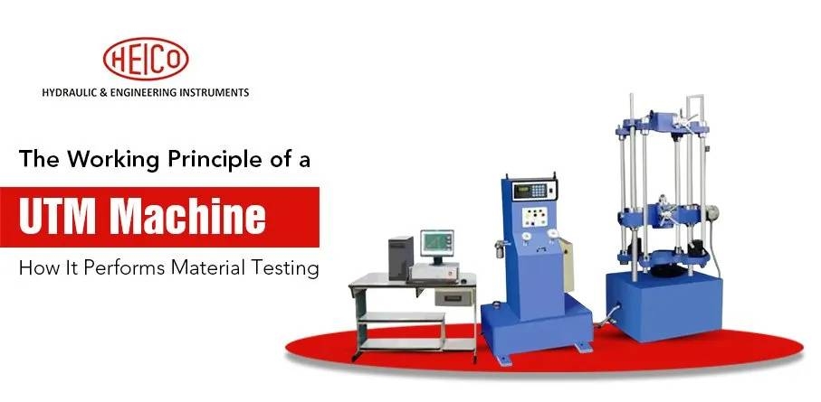
The kinematic diagram of the machines consists of a base and a load frame installed on it, made in a single-column (with one screw transmission) or two-column (with two screw transmissions) design, a set of grips (in the basic model – 1 set) and (or) special mechanical devices for installing the test sample, a force-measuring sensor, a movable crosshead displacement sensor, a block of emergency limit switches, a push-button station. The base of the machines contains a servo-drive loading system, a block of microprocessor control and measurement controllers, and elements of protective and switching equipment.
The load frame consists of a lower plate, fixed (upper), and movable cross-beams, as well as guide columns and lead screw transmissions installed inside it to ensure movement of the movable cross-beam. The passive gripper can be installed on the lower plate or fixed (upper) cross-beam. The speed of movement of the movable cross-beam is controlled and regulated using a microprocessor controller unit and a servo drive system. The push-button station is used to control (set) the positioning of the movable cross-beam.
Sensor Placement and Signal Processing
The force-measuring sensor can be installed: on the lower plate of the machine base, the movable or fixed (upper) cross-beam, depending on the machine version.
The displacement sensor (angular or linear displacement converter) is installed using a vibration-damping clutch above or below one of the screws. Measuring the movement of the movable cross-beam is based on the transformation of the rotational motion of the lead screw by the displacement sensor into a pulse signal proportional to the distance traveled by the movable cross-beam.
The microprocessor control and measurement controller unit receives, processes and stores signals from the measuring system sensors: force-measuring, moving crosshead, limit switch unit, and also generates signals for controlling the testing process. This unit contains the metrologically significant part of the Material testing machine software.
Visit Us for More Information:- https://heicoin.com/blog/the-working-principle-of-a-utm-machine-how-it-performs-material-testing/
- Questions and Answers
- Opinion
- Motivational and Inspiring Story
- Technology
- Live and Let live
- Focus
- Geopolitics
- Military-Arms/Equipment
- Segurança
- Economy
- Beasts of Nations
- Machine Tools-The “Mother Industry”
- Art
- Causes
- Crafts
- Dance
- Drinks
- Film/Movie
- Fitness
- Food
- Jogos
- Gardening
- Health
- Início
- Literature
- Music
- Networking
- Outro
- Party
- Religion
- Shopping
- Sports
- Theater
- Health and Wellness
- News
- Culture

